Index Menu
Back
Main Menu
Forward
 
TUTORIAL: How to Model a Real 3D Knot
 
                                    P  R  E  M  I  S  E

The goal is to model a real 3D Knot with Lightwave © Modeler, of Newteck Inc. ©, without help 
of anyone plugin,  but only with the tools  and  the options supplied with the basis program. 
This tutorial  is good either for Pc  or  for MacIntosh computers.  Click with mouse on small 
picture near the words and you can see them more large.  
                                 P  R  O  C  E  D  U  R   E

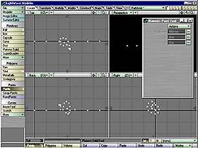
Open Lightwave Modeler ©  and  click  inside  any window 
with left mouse button.  Go to  "Create" menu,  click on 
left, in "Points" submenu,  on "Points" button and after 
open the "Numeric" Panel  (from keyboard "N").  Click on 
Actions/Activate  and  activate this panel. Insert these 
coordinates  to create your first point: X=0 mm, Y=0 mm, 
Z=0 mm.  Press Return  and  the first point will be full 
operative. Click on "Points" (from keyboard "+") and  go 
to "Numeric" Panel  to insert coordinates  of the second 
point.  In all you will must create 20 points. So repeat 
the same operation  for every following point.  Remember 
to use millimeters (mm) as measure unit. 
Image01
Image02

 The  settings  of  the  following  19  points are these: 
    Point 02:     X= 100 mm,    Y= 0  mm,    Z= 0  mm. 
    Point 03:     X= 220 mm,    Y= 5  mm,    Z=-5  mm. 
    Point 04:     X= 250 mm,    Y= 60 mm,    Z=-10 mm. 
    Point 05:     X= 270 mm,    Y= 75 mm,    Z=-30 mm. 
    Point 06:     X= 290 mm,    Y= 60 mm,    Z=-60 mm. 
    Point 07:     X= 300 mm,    Y= 30 mm,    Z=-70 mm. 
    Point 08:     X= 300 mm,    Y= 0  mm,    Z=-60 mm. 
    Point 09:     X= 295 mm,    Y=-20 mm,    Z=-35 mm. 
    Point 10:     X= 285 mm,    Y=-30 mm,    Z=-3  mm. 
    Point 11:     X= 265 mm,    Y=-20 mm,    Z= 20 mm. 
    Point 12:     X= 240 mm,    Y= 5  mm,    Z= 30 mm. 
    Point 13:     X= 220 mm,    Y= 30 mm,    Z= 20 mm. 
    Point 14:     X= 210 mm,    Y= 45 mm,    Z= 0  mm. 
    Point 15:     X= 220 mm,    Y= 45 mm,    Z=-25 mm. 
    Point 16:     X= 245 mm,    Y= 30 mm,    Z=-35 mm. 
    Point 17:     X= 275 mm,    Y= 15 mm,    Z=-30 mm. 
    Point 18:     X= 340 mm,    Y= 5  mm,    Z=-5  mm. 
    Point 19:     X= 450 mm,    Y= 0  mm,    Z= 0  mm. 
    Point 20:     X= 550 mm,    Y= 0  mm,    Z= 0  mm. 

In  "Points"  selection  mode  (from keyboard "Ctrl+G"), 
select with mouse,  one at one,  in sequence, all the 20 
points, starting,  on the left,  from point number 1 and 
ending,  on the right,  with the point number 20.  After 
set "Poligons"  selection mode  (from keyboard "Ctrl+H") 
and click on "Construct/Open Curves" (or press "Ctrl+P") 
Save the Path you have created with name "Pathknot.lwo". 
If you don't have  the patience  to create the necessary 
points, click here on PathKnot.zip, download, unpack and 
load it into a new level of your Modeler. 
Image03
Image04

 Change Layer, that is click on layer near the one you've 
 worked until now,  go to "Create" menu,  click on "Disc" 
 and after this open "Numeric" Panel (from keyboard "N"). 
 Then select "Actions/Activate",  to activate  this panel 
 and insert these values: Axis= X, Sides= 24, Segments= 1 
 Radius Y= 25 mm,  Radius Z= 25 mm.  Insert  value "0" in 
 all other fields  of the panel.  Press Return  and after 
 close "Numeric" panel. 

Click  on  "Modify/Texture/Surface"  (from keyboard "Q") 
and  open so  the "Change Surface" panel.  Insert  a new 
name,  that is "Knot" at the Disc  you had just created, 
set color, with "Select Color" in "Quick Color" way, and 
insert these values: R(ed)=210, G(reen)=190 e B(lue)=77. 
Give OK e after set Diffuse=75, Specular=25 and click on 
"Smoothing" to make it operative. 
Image05
Image06

 Click up  on the left on "Surface Editor",  after select 
 "Knot" and insert these others values: "Glossiness"= 64,  
 "Smooth Threshold"= 59,5. 

Come back  to main menu of the Modeler,  click only once 
on "Modify/Orientation/Flip Polygons" (or press "F"), to 
orientate correctly the face of your Disk called "Knot", 
then  set  as Main Layer  the one  with the Disk  and as 
Secondary Layer  the one  with the Path.  Click after on 
"Multiply/Rail Extr"  (from  keyboard  "Ctrl+R"),  leave 
factory  settings,  that  is "Segments = Automatic"  and 
"Oriented=Yes". Give OK. 
Image07
Image08

 Now the whole knot will appear on your screen. Obviously 
 you can  modify  lightly  the values  of the 20 starting 
 points  and  so personalize your "Knot",  otherwise also 
 insert different values  of "Surface Editor",  to change 
 the color and the other attributes of Texturing. 

But your knot  has its string  a few too much short,  so 
you must lengthen its ends. Go in "Polygons" select mode 
(from keyboard "Ctrl+H") and select only the left end of 
your string,  making a circle  around it with your right 
mouse. After flip the side of this polygon,  pushing the 
key "F", or clicking "Modify/Orientation/Flip Polygons". 
Select "Multiply/Extrude" (from keyboard "Ctrl+H"), then 
"Numeric"  (from keyboard "N")  and  n this panel enable 
"Actions/Activate"   and   modify   only  these  values: 
Extent: X=-500 mm, Y=0, Z=0. Sides=20. Give OK. 
Image09
Image10

 But a superfluous polygon remains where you extruded the 
 string.  So you  must  select again  the same polygon as 
 before  the extrude operation,  always  making  a circle 
 around it with your right mouse,  and after this erasing 
 it,  clicking down at the center of your screen on "Cut" 
 (from keyboard "X"). 

Repeat  the same operation  than before,  but now on the 
right, that is on the other end of your string, making a 
circle  around  it  with  your right mouse.  In this way 
select  the  last  polygon  on the right,  flip it (from 
keyboard "F"), select  "Multiply/Extrude" (from keyboard 
"Ctrl+H"),  then "Numeric"  (from keyboard "N"). In this 
panel  enable  "Actions/Activate" and  modify only these  
values:  Extent: X=500 mm, Y=0, Z=0. Sides=20.  Give OK. 
Image11
Image12

 Also here  a superfluous polygon remains  where you have 
 extruded the string.  So you must select  again the same 
 polygon as before the extrude operation, always making a 
 circle around it  with your right mouse,  and after this 
 erasing it,  clicking down  at the center of your screen 
 on "Cut" (from keyboard "X").  Save now the whole object 
 with the name "NodoKnot.lwo". 

Come out  of "Surface Editor" menu  and  you will see on 
Go  to  "View/Options/Options"  (from keyboard "D")  and 
set "Layout" = Single and "Background  Color" = 0, 0, 0. 
Deselect "Show Grid" option, give OK. Increase a few the 
"Zoom In" (from keyboard "."), and at the end enjoy with
 your Three-dimensional Knot! 
Image13


Indietro
 
Avanti

I have written this page in Italian language and after I have translated it in English language.
If you find some my translation's error, excuse me and send me an e-mail with the correct version. Thanx !!
Please Remember That Everything On This Web Site Is Copyrighted.


All rights reserved. Copyright © 2000 by Francesco Franceschi.